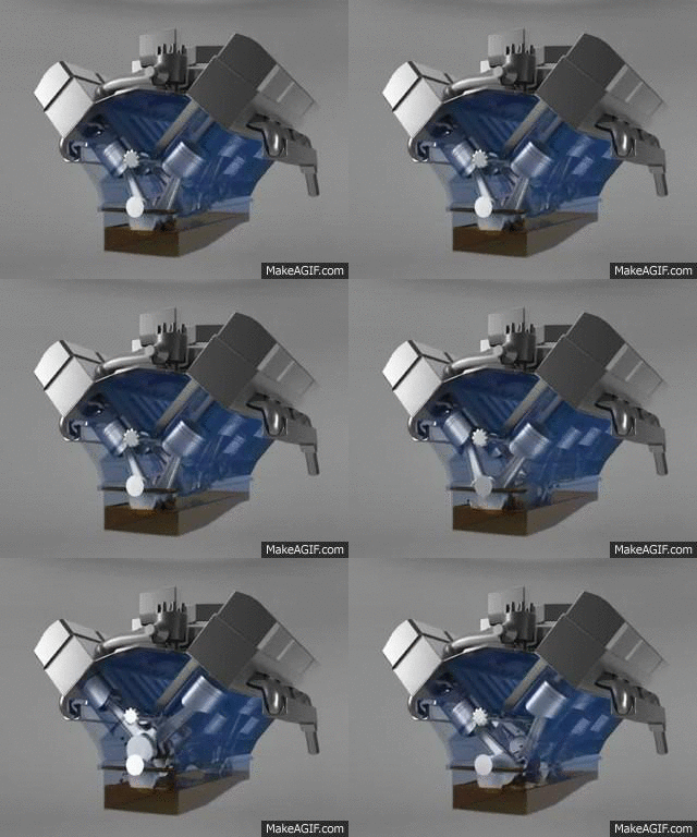
Methods of Lubrication in IC Engine

 The various methods adopted for lubrication Of  I.C Engines are :

i) Petrol lubrication or mist lubrication system,

ii) Wet sump system, and 

iii) Dry sump system. 


I) Petrol or Mist Lubrication System :

   It is simplest of all types of lubrication. This method is used in light vehicles such as motor cycles and scooters. About 3 to 6 % of lubricating oil is mixed with petrol in fuel tank. Here, there is no separate sump and pump. The oil mixing with petrol acts as lubricant. 

The disadvantage of  this method is, if the engine remains idle for the long time, the oil will get separated and cause clogging of fuel passage in carburetor there by resulting in starting trouble. If the quantity of mixing oil is less, lubricating is insufficient which causes damage to the engine. If the quantity of oil is more, it will release more carbon deposits in the cylinder. So, the engine will give dark smoke.


II) Wet Sump System :

   In this method, the lubrication oil is stored in the oil sump. From the oil sump, the oil is supplied to various parts of  the engine. This system may be further classified as :

a) Gravity Lubrication System 

b) Splash Lubrication System

c) Pressure Lubrication System

d) Semi - pressure Lubrication System


III) Dry Sump Lubrication System :

     The lubricating oil stored in the oil sump is called wet sump system. But the system in which the lubricating oil is not kept in the oil sump is known as dry sump system. In this system, oil is carried in a separate tank and fed to the engine.

     The oil which falls into the oil sump after lubrication is sent back to oil tank by a separate delivery pump. Thus the system consists of two pumps. One pump is used to feed the oil. The other pump is used to deliver the oil to the oil tank. This system is used in aircrafts.

     The main advantage of  this system is that there is no chance of break down in the oil supply during up and down movement of  the vehicle.    

Comments

Popular posts from this blog

THROTTLE GOVERNING OF STEAM TURBINES

Steam Pressure at inlet to a steam turbine is reduced by throttling process to maintain the speed of the  turbine constant at part load and hence this method of governing is called "Throttle Governing".  Construction : Throttle governing system consists of  a centrifugal governor, a lever , an oil pump , a pilot piston , control valve , a relay piston and a throttle valve. The throttle valve is moved by a relay piston. The relay piston is actuated by pilot piston control valve. There are two piston valves covering ports in the pilot piston control valve without any overlap. These piston valves are operated by lubricating oil supplied by a gear pump at 2 to 4 bar. The oil returns to the drain from this chamber.  Working : When the turbine works on full rated load, the throttle valve will remain open. When the load is decreased, the energy output of the turbine becomes in excess and the turbine shaft speed increases. Hence, governor sleeve will lift. The upward movement of the

ELECTRICAL COMPARATORS AND ITS WORKING

Electrical Comparators are used as a means of  detecting and amplifying small movements of a work contacting elements. An electrical comparator consists essentially of  a pick-up head or transducer for converting a displacement into a corresponding change in current and a meter or recorder connected in the circuit to indicate the electrical change, calibrated to show in terms of displacement. Generally, an amplifier is needed to provide the requisite sensitivity and to match the characteristics of different parts of  the circuit. Electrical comparators can be classified according to the electrical principle used in the pick-up head. Most of the comparators use either a differential transformer, an inductance bridge, a strain gauge or a capacitor as a means of detecting movement of the gauging element. There are different types of  electrical comparators. One kind called an electrolimit gauge is used to check or measure the outside diameter of a  roll. The object to be checked is place

MELTING FURNACES FOR FERROUS METALS : CUPOLA AND ITS WORKING

Various types of melting furnaces are used in different foundry shops, depending upon the quantity of metal to be melted at a time, and the nature of work that is carried out in the shop.  The primary objective in cupola is to produce iron of desired composition, temperature and properties at the required rate in the most economical manner. Besides, this furnace has many distinct advantages over the other types, e.g., simplicity of operation, continuity of production, and increased output coupled with a high degree of efficiency.  Description Of a Cupola : The Cupola Furnace consists of a vertical, cylindrical steel sheet, 6 to 12 mm thick, and lined inside with acid refractory bricks or acid tamping clay. The refractory bricks or the tamping clay used consist of  silicon oxide acid (SiO2) and alumina (Al2O3). The lining is generally thicker in the lower where the temperatures encountered are higher than in the upper region. The shell is mounted either on a brick work foundation or on